
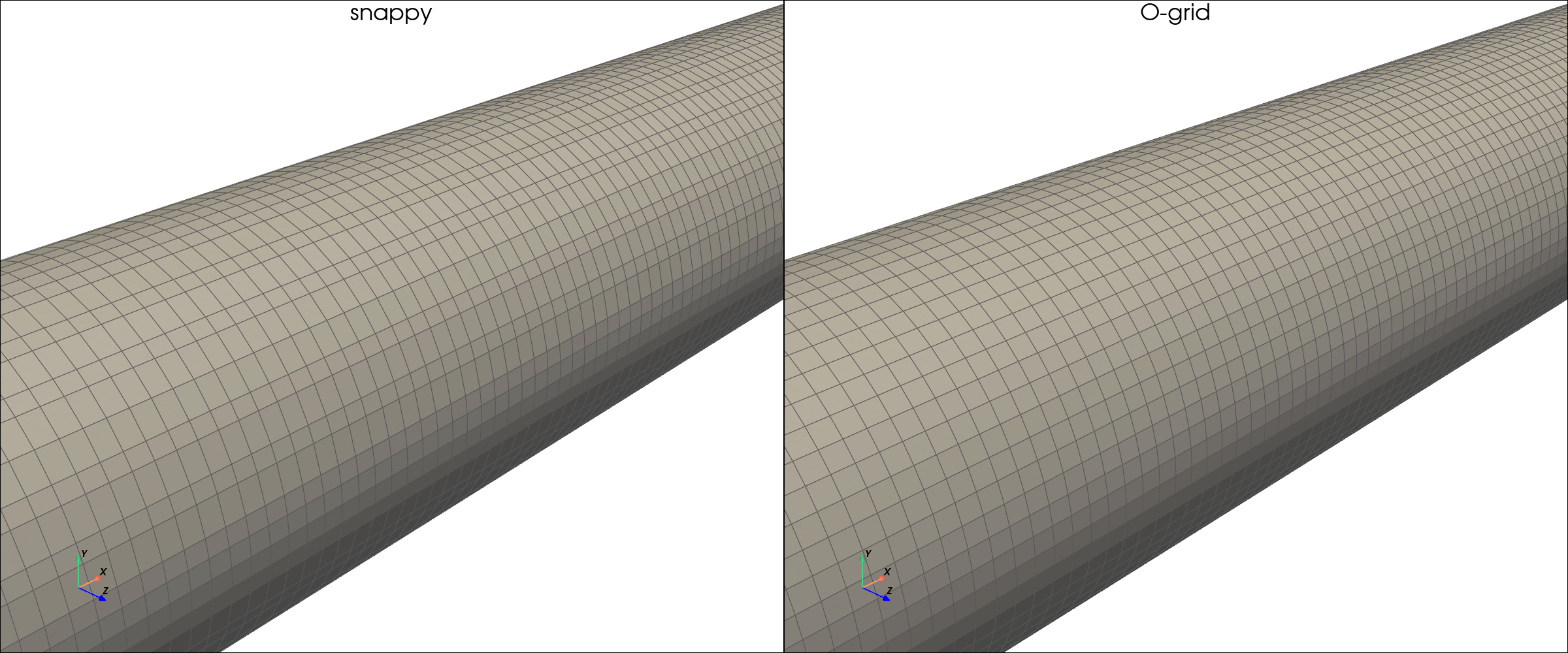
Every CFD engineer who has meshed a pipe with snappyHexMesh knows the problem: the circular wall comes out as a staircase. The cut-cell algorithm is fundamentally Cartesian — it cannot represent a curved surface without approximating it as a series of axis-aligned steps.
For external aerodynamics this barely matters (snap and smooth recover most of the surface). But for internal pipe flow where the wall boundary layer is the physics — where wall shear stress, pressure drop, and heat transfer all depend on resolving the near-wall gradients on a clean surface — the staircase is not cosmetic. It's a source of error.
AuraMesh solves this with a body-fitted butterfly O-grid that gives a mathematically perfect circular wall, structured radial grading, and zero snappyHexMesh involvement.
The Comparison: Same Pipe, Two Approaches
A straight circular pipe (R = 0.05 m, L = 0.5 m) meshed at the same effective resolution by two methods:
| snappyHexMesh (cut-cell) | AuraMesh O-grid (body-fitted) | |
|---|---|---|
| Method | Cartesian background + surface snap | Butterfly blockMesh projected onto searchableExtrudedCircle |
| Wall shape | Approximate (saw-tooth) | Exact circle |
| Near-wall cells | Irregular, no radial structure | Structured radial grading |
| Boundary layer | Requires prism-layer addition (can collapse) | Built into the radial grading (never collapses) |
| snappyHexMesh | Required | Not used |
| Cells | 32,479 | 64,000 |
The Inlet Face — Zoomed
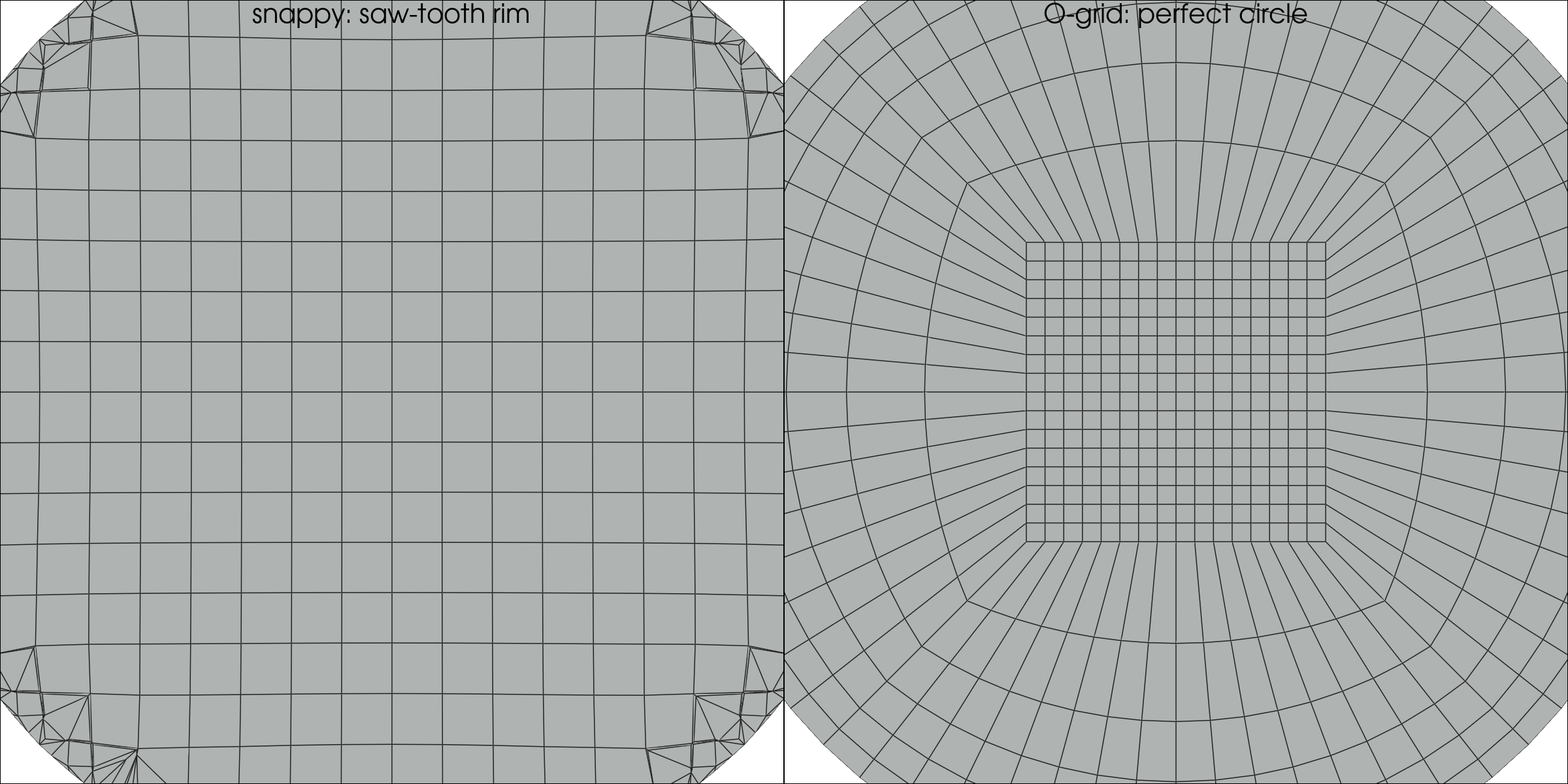
The difference is immediately visible. The snappy mesh (left) approximates the circle with axis-aligned steps — every corner is a potential source of numerical noise in the wall shear stress. The O-grid (right) is a perfect circle with cells radiating inward, getting progressively finer toward the wall.
Full Cross-Section
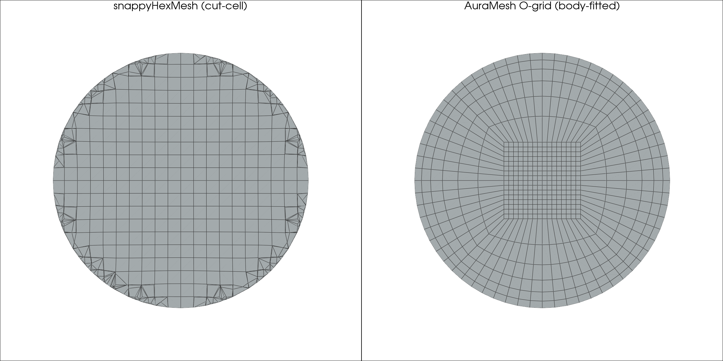
The full cross-section reveals the structural difference. The O-grid's butterfly topology (a square center block surrounded by four radial sectors) is the same approach used in turbomachinery meshing — proven over decades to give optimal boundary-layer resolution on curved surfaces.
3D Surface View
The Physics Payoff: Velocity Profile
It's not just prettier. The structured radial grading resolves the boundary layer correctly.
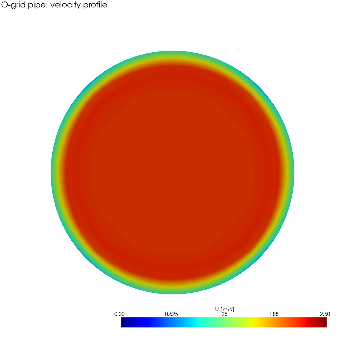
The velocity cross-section at mid-pipe shows a smooth, continuous developing-flow profile: zero at the wall (no-slip), accelerating through the boundary layer, and reaching the core velocity of ~2.26 m/s (above the inlet 2.0 m/s due to displacement thickness). This smoothness is a direct consequence of the radial grading — the wall-adjacent cells are fine enough to resolve the gradient without interpolation artifacts.
On the snappy mesh, the same profile would show oscillations at the wall due to the staircase geometry exciting numerical noise in the wall-normal gradient.
How It Works
AuraMesh detects that the input STL is a clean circular pipe (axis-aligned, constant radius, exactly two flat circular caps, no internal obstacles) and automatically routes to the O-grid path:
The radial wall grading (0.27 here) is solved from the target y⁺ — the same flat-plate Cf model used for snappy's prism layers, but applied as the O-grid's radial simpleGrading. The boundary layer is built into the mesh topology, not added as a fragile post-hoc layer.
Beyond Straight Pipes
The same O-grid technology extends to:
| Geometry | Method |
|---|---|
| Straight pipe / cylinder | searchableExtrudedCircle + 2-point centerline |
| Bent pipe (90° elbow, S-bend, 3D compound curve) | Swept butterfly along a marched centerline with rotation-minimizing frame |
| Tapered pipe | Per-station scaled radius (analytic profile) |
| Oval / elliptic duct | Per-station ellipse with arc edges |
All of these are pure blockMesh — no snappy, no cut-cells, no prism-layer collapse. The detection is automatic: --background auto identifies the geometry class and routes to the appropriate template.
When to Use Each Approach
| Use the O-grid when... | Use snappy when... |
|---|---|
| Geometry is a circular pipe/duct (straight or bent) | Geometry is arbitrary (car, building, room) |
| Wall shear stress / heat transfer accuracy matters | Global flow pattern is the target |
| The boundary layer IS the physics (pipe flow, Poiseuille, heat exchangers) | The BL is secondary to separation / wake |
| You need the mesh to never fail (no layer collapse) | Complex multi-body assemblies |
AuraMesh picks the right one automatically. One flag (--background auto) handles both.
In this series: Ahmed Body Aerodynamics | Clean Room Airflow | Pedestrian Wind Comfort | Body-Fitted Pipe Meshing | Vortex Shedding Animation